Samsung ME16H702SES Manual: Comprehensive Guide
This comprehensive guide details the Samsung ME16H702SES microwave‚ offering insights from official manuals‚ parts diagrams‚ and repair resources available online today.
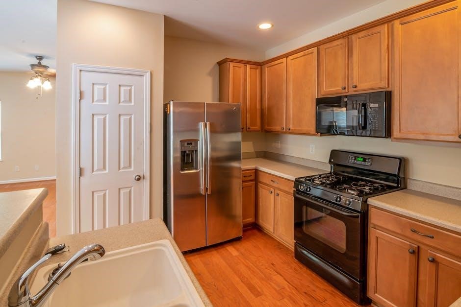
The Samsung ME16H702SES is a 1.6 cu. ft. over-the-range microwave‚ known for its big door design and efficient ventilation system. This manual serves as a complete resource for owners‚ covering everything from initial setup and safe operation to troubleshooting and maintenance. Access to the official user manual (DE68-03587B-08_IM_ME16A4021_OTR_EN_CFR_241216.pdf) is readily available through Samsung’s download center and platforms like ManualsLib and the Internet Archive.
Users can find installation instructions‚ parts diagrams‚ and repair assistance at Sears PartsDirect and PartSelect.com‚ ensuring a seamless experience with this appliance.
Safety Precautions
Prioritize safety when operating the Samsung ME16H702SES microwave. Always ensure proper grounding via a dedicated electrical connection‚ adhering to specified voltage requirements. Never operate the microwave empty‚ as this can damage the magnetron. Exercise caution when heating liquids to prevent delayed-boiling eruptions.
Regularly inspect the power cord for damage and avoid using extension cords. Keep the ventilation system clear of obstructions to prevent overheating. Refer to the official manual for detailed safety warnings and notices regarding installation and usage to ensure safe operation.
Package Contents & Initial Inspection
Upon receiving your Samsung ME16H702SES microwave‚ carefully inspect the packaging for any signs of damage during transit. The package should include the microwave oven itself‚ a glass turntable‚ a turntable support ring‚ an installation bracket‚ and this user manual.
Verify all components are present and undamaged. If any parts are missing or appear faulty‚ immediately contact Samsung customer support or the retailer. Do not attempt to install or operate a damaged microwave. Retain the original packaging for potential returns or warranty claims.
Installation Instructions

Proper installation of your Samsung ME16H702SES is crucial for optimal performance and safety. Before beginning‚ ensure the wall is structurally sound and capable of supporting the microwave’s weight. Refer to the detailed installation manual (DE68-03587B-08) for specific bracket mounting instructions.
Confirm adequate ventilation and adherence to electrical connection requirements. Incorrect installation can lead to malfunction or hazard. Always prioritize safety and consult a qualified technician if unsure about any step of the process.
Mounting the Microwave
Securely mounting the Samsung ME16H702SES requires a dedicated mounting bracket‚ often sold separately or included with specific installation kits. The official installation manual (DE68-03587B-08) provides detailed diagrams illustrating bracket placement and screw specifications. Ensure the bracket is firmly attached to wall studs for maximum stability.
Carefully align the microwave with the bracket‚ ensuring it’s level before fully engaging the mounting hooks. Double-check all connections before releasing the microwave to prevent accidental falls. Proper mounting is vital for safe operation.
Electrical Connection Requirements
The Samsung ME16H702SES operates on a standard 120V‚ 60Hz electrical supply. A dedicated 15-amp circuit is recommended to prevent overloading. The appliance must be properly grounded via a three-prong plug. Never use extension cords or adapters‚ as they pose a safety hazard.
Ensure the outlet is easily accessible for disconnection in emergencies. Consult a qualified electrician if your outlet doesn’t meet these requirements or if you’re unsure about the electrical installation. Improper wiring can lead to malfunction or fire.
Ventilation Requirements
Proper ventilation is crucial for the Samsung ME16H702SES’s optimal performance and longevity. This over-the-range microwave expels steam and cooking odors. Ensure adequate airflow by maintaining a minimum clearance of 3 inches around the unit‚ especially at the sides and rear.
Avoid blocking the ventilation openings. Regularly inspect and clean the vent filters to maintain efficient airflow and prevent grease buildup. Insufficient ventilation can lead to condensation‚ reduced cooking efficiency‚ and potential damage to surrounding cabinetry.
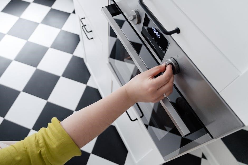
Control Panel Overview
The Samsung ME16H702SES features an intuitive control panel designed for ease of use. It incorporates both physical buttons and a digital display. Buttons allow direct access to common functions like power level‚ cooking time‚ and auto cook programs. The display clearly shows the selected settings‚ remaining cook time‚ and any active sensor cooking information.
Understanding the panel’s layout is key to maximizing the microwave’s capabilities. Familiarize yourself with each button’s function to efficiently navigate the various cooking options and customize your cooking experience.
Buttons and Their Functions
The control panel’s buttons offer precise control over cooking. ‘Power Level’ adjusts microwave intensity‚ while ‘Cook Time’ sets the duration. ‘Auto Cook’ initiates pre-programmed settings for common foods. ‘Defrost’ allows thawing based on weight or time. ‘Sensor Cook’ utilizes humidity sensing for optimal results. ‘Start’ begins the cooking cycle‚ and ‘Stop/Clear’ halts operation or resets settings.
Additional buttons may include options for popcorn‚ reheat‚ or specific food types. Refer to the full manual for a detailed explanation of each button’s unique function and capabilities.
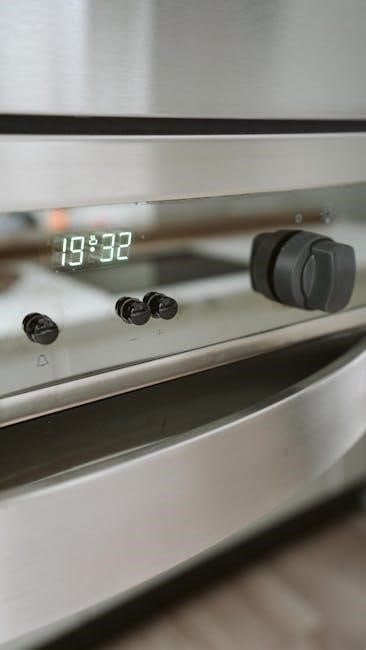
Display Indicators
The Samsung ME16H702SES display provides crucial information during operation. A clock displays the current time‚ while cooking time remaining is prominently shown. Indicators signal when the microwave is actively heating or in defrost mode. Error codes appear to alert users to potential issues‚ requiring troubleshooting. The power level is also visually represented on the display.
Sensor cooking progress is often indicated‚ and a ‘Done’ message signals cycle completion. Consult the manual for a complete decoding of all display symbols and error messages.
Operating Instructions
To begin using your Samsung ME16H702SES‚ familiarize yourself with the control panel. Press the ‘Clock’ button to set the current time‚ essential for accurate cooking durations. For basic microwave cooking‚ enter the desired time and power level. Utilize the ‘Auto Cook’ functions for pre-programmed settings for common foods. Explore sensor cooking for optimal results‚ automatically adjusting cooking time based on humidity.
Always refer to the manual for detailed instructions on each function and safety precautions during operation.
Setting the Clock
Accurate timekeeping is crucial for proper microwave operation. To set the clock on your Samsung ME16H702SES‚ first‚ press the ‘Clock’ button. The display will show the current hour and begin to flash. Use the numeric keypad to enter the correct hour‚ ensuring AM or PM is selected. Press ‘Clock’ again to confirm the hour.
Next‚ the minutes will flash; enter the correct minutes using the keypad and press ‘Clock’ one final time to save the setting. A properly set clock ensures accurate cooking and timer functions.
Microwave Cooking Basics
For optimal results with your Samsung ME16H702SES‚ understand basic microwave cooking. Always use microwave-safe containers – glass‚ ceramic‚ and some plastics are suitable. Avoid metal‚ as it can cause sparking and damage. Food cooks from the outside in‚ so stirring or rotating dishes mid-cooking ensures even heating.
Power levels affect cooking speed; lower levels are ideal for delicate foods or defrosting. Utilize the turntable for consistent cooking. Cover food to retain moisture and prevent splattering‚ using a microwave-safe lid or vented plastic wrap.
Using Auto Cook Functions
The Samsung ME16H702SES features convenient Auto Cook functions for popular dishes. These pre-programmed settings automatically adjust cooking time and power levels for optimal results. Access these functions via the control panel‚ selecting the appropriate food category and weight.
Refer to the user manual for a complete list of Auto Cook options and recommended weight ranges. While convenient‚ monitor food during auto-cooking‚ as results can vary based on food density and starting temperature. Adjust cooking time slightly if needed for your preference;
Sensor Cooking Guide
The Samsung ME16H702SES utilizes sensor cooking technology to automatically determine the optimal cooking time based on humidity levels within the microwave. This ensures food is cooked thoroughly without over or undercooking. To use‚ simply select the sensor cook function‚ choose the food type‚ and press start.
The microwave will monitor steam emitted during cooking‚ adjusting time accordingly. For best results‚ avoid opening the door during sensor cooking. Refer to the manual for specific food recommendations and ensure proper food placement for accurate sensor readings.
Defrosting Functions
The Samsung ME16H702SES offers several defrosting functions for convenient and efficient thawing of frozen foods. Weight defrost allows you to enter the food’s weight for precise thawing‚ while time defrost lets you specify a defrosting duration. For optimal results‚ remove food from any packaging before defrosting.
It’s recommended to use the ‘Defrost’ function for items like meat‚ poultry‚ and seafood. Stirring or rotating the food halfway through the defrosting cycle promotes even thawing. Always cook food immediately after defrosting to ensure food safety.
Ventilation System Operation
The Samsung ME16H702SES microwave’s ventilation system effectively removes steam‚ odors‚ and grease while cooking. It operates with multiple fan speed settings‚ allowing you to adjust the ventilation level based on your cooking needs. Higher speeds are ideal for frying or boiling‚ while lower speeds suffice for reheating.
Regular filter replacement is crucial for maintaining optimal performance. The charcoal filter traps grease and odors‚ and should be replaced periodically – typically every 6 months – depending on usage. A clean filter ensures efficient ventilation and prevents unpleasant smells.
Fan Speed Settings
The ME16H702SES microwave offers a versatile ventilation system with multiple fan speed settings. Typically‚ these include a Low‚ Medium‚ and High option‚ selectable directly from the control panel. The Low setting is suitable for simmering or warming food‚ minimizing noise while providing gentle ventilation. Medium is ideal for everyday cooking tasks‚ effectively removing steam and odors.
High speed is recommended for intense cooking like frying or grilling‚ maximizing smoke and grease removal. Some models may also feature an automatic setting that adjusts fan speed based on cooking intensity.
Filter Replacement
Maintaining optimal ventilation requires periodic filter replacement in your Samsung ME16H702SES microwave. Grease filters trap airborne particles‚ preventing them from recirculating. These filters‚ usually charcoal or mesh types‚ should be inspected regularly – approximately every three months with average use. A clogged filter reduces ventilation efficiency and can pose a fire hazard.
Replacement filters are readily available through Samsung’s parts website or authorized retailers. The process typically involves removing the old filter and snapping in the new one. Refer to the user manual for specific instructions.
Care and Cleaning
Regular care ensures your Samsung ME16H702SES microwave remains hygienic and performs optimally. For exterior cleaning‚ use a damp cloth and mild detergent; avoid abrasive cleaners that could damage the finish. The control panel can be wiped clean similarly. Interior cleaning is crucial; routinely wipe down the interior with a damp cloth after each use to prevent food buildup.
For stubborn stains‚ heat a cup of water with lemon juice for a few minutes‚ then wipe clean. Remember to always unplug the microwave before cleaning and ensure it’s completely dry before reuse.
Exterior Cleaning
Maintaining the exterior of your Samsung ME16H702SES microwave is simple. Begin by unplugging the unit for safety. Use a softly dampened cloth with a mild dish soap solution to wipe down the cabinet surfaces. Avoid abrasive cleaners‚ scouring pads‚ or harsh chemicals‚ as these can scratch or discolor the finish. Pay attention to the control panel‚ gently wiping away any spills or splatters.
Rinse with a clean‚ damp cloth and dry thoroughly. For stainless steel models‚ use a stainless steel cleaner for optimal shine and protection against fingerprints.
Interior Cleaning
Regular interior cleaning keeps your Samsung ME16H702SES functioning efficiently. Unplug the microwave first! A simple method involves heating one cup of water with a tablespoon of vinegar for several minutes to loosen food splatters. Allow the steam to condense before carefully wiping down the interior with a soft cloth. Avoid harsh abrasives.
For stubborn residue‚ create a baking soda paste and gently scrub. Ensure all traces of cleaning solution are removed before reuse. The turntable and roller ring are removable and dishwasher-safe for convenient cleaning.
Troubleshooting Common Issues
If your Samsung ME16H702SES isn’t heating‚ verify the door is securely closed – a common cause. Check the power cord and circuit breaker. Display errors require consulting the user manual for specific codes and solutions. If issues persist‚ resetting the microwave by unplugging it for a few minutes can sometimes resolve minor glitches.
For persistent problems‚ referencing parts diagrams (available on Sears PartsDirect and PartSelect.com) can aid in identifying potential component failures. Always prioritize safety and consider professional repair if uncomfortable with internal diagnostics.
Microwave Not Heating
If the Samsung ME16H702SES fails to heat‚ first ensure the door closes completely; the safety interlock prevents operation if ajar. Verify the power cord is firmly connected and the circuit breaker hasn’t tripped. Attempt resetting the microwave by disconnecting it from power for several minutes. If the issue continues‚ inspect the waveguide cover inside the oven for damage or debris‚ as this can impede microwave transmission.
Consult the user manual for specific troubleshooting steps and error codes. For complex issues‚ professional repair is recommended‚ utilizing parts from sources like Sears PartsDirect.
Display Errors
Should the Samsung ME16H702SES display an error code‚ consult the user manual for a detailed explanation of each code’s meaning. Common errors may indicate sensor malfunctions‚ door switch problems‚ or internal component failures. Attempting a reset – disconnecting the microwave from power for a few minutes – can sometimes clear temporary errors.
Document the specific error code before contacting customer support or seeking repair. Resources like Repair Help ─ PartSelect.com offer symptom-based troubleshooting‚ potentially aiding diagnosis before professional intervention is needed.
Parts Diagram & Replacement
Locating parts diagrams for the Samsung ME16H702SES is crucial for repairs. Sears PartsDirect provides manufacturer-approved parts and diagrams‚ ensuring a proper fit; These diagrams illustrate component locations‚ aiding in disassembly and reassembly. When replacing parts‚ always disconnect the microwave from power.
Common replacement parts include the turntable motor‚ waveguide cover‚ and door switches. PartSelect.com offers OEM parts and instructional videos to guide the replacement process. Prioritize genuine Samsung parts for optimal performance and safety.
Warranty Information
Samsung provides a warranty for the ME16H702SES microwave‚ though specific terms vary by region and retailer. Generally‚ the warranty covers defects in materials and workmanship for a defined period‚ typically one year for parts and labor.
Review your purchase documentation for detailed warranty coverage. Registering your appliance with Samsung may streamline the claims process. The warranty doesn’t cover damage from misuse‚ improper installation‚ or unauthorized repairs. Contact Samsung customer support for warranty claims and service options.
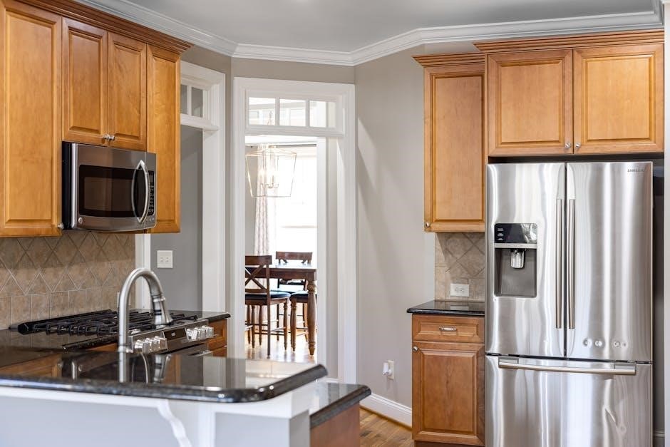
Technical Specifications
The Samsung ME16H702SES is an over-the-range microwave boasting a 1.6 cubic foot capacity. Its dimensions and weight aren’t explicitly detailed in readily available resources‚ but it’s designed for standard over-range installation. Power consumption details are also limited in public specifications.
However‚ it operates on standard household electrical voltage. This model features a big door design for enhanced visibility and convenience. Further technical details‚ including specific wattage and frequency‚ can be found within the official user manual available for download from Samsung’s support website.
Dimensions and Weight
Specific dimensions and weight for the Samsung ME16H702SES are not prominently featured in the readily accessible online documentation. As an over-the-range microwave‚ it’s designed to fit standard cabinetry cutouts‚ typically around 30 inches wide. Detailed measurements—height‚ depth‚ and exact weight—are best obtained from the official Samsung product manual.
These specifications are crucial for ensuring proper installation and verifying compatibility with existing kitchen spaces. The manual provides precise figures necessary for a secure and aesthetically pleasing fit‚ avoiding potential installation issues.
Power Consumption
The Samsung ME16H702SES microwave’s power consumption details aren’t explicitly stated in the brief online resources. However‚ typical over-the-range microwaves with a 1.6 cu. ft. capacity generally range between 1000-1200 watts for microwave cooking power. The total power draw‚ including the ventilation fan and display‚ will be higher.
Consulting the official user manual is essential for precise wattage information. Understanding power consumption helps estimate energy costs and ensures the microwave is compatible with your kitchen’s electrical circuit capacity‚ preventing overloads.
Frequently Asked Questions (FAQ)
Q: Where can I download the official manual? A: The Samsung Download Center (org.downloadcenter.samsung.com) hosts the ME16H702SES manual (ME16H702SE_AA_AC_EN-CFR.pdf). Q: Where can I find replacement parts? A: Sears PartsDirect (searspartsdirect.com) and PartSelect.com offer OEM Samsung parts. Q: Is installation support available? A: ManualsLib provides the installation instructions manual.
Q: What if my microwave isn’t heating? A: Refer to the troubleshooting section within the full user manual for guidance. Further assistance is available through Samsung Support.
Customer Support Contact Information
For direct assistance with your Samsung ME16H702SES microwave‚ please visit the official Samsung Support CA website. While specific contact details aren’t explicitly provided in the sourced information‚ the Samsung website is the primary resource. You can typically find phone numbers‚ live chat options‚ and email support forms there.
Additionally‚ exploring online communities and forums dedicated to Samsung appliances may offer peer-to-peer support and troubleshooting advice. Remember to have your model number readily available when contacting support.
Downloading the User Manual
The official Samsung ME16H702SES user manual is readily available for download. A direct link‚ provided by Samsung’s download center‚ leads to the “DE68-03587B-08_IM_ME16A4021_OTR_EN_CFR_241216.pdf” file. This document‚ version 0.7 and 8.06MB in size‚ supports both English and French languages.
Access is available through the Samsung website‚ specifically for Canadian (CA) and US regions. The Internet Archive also offers a copy for borrowing and streaming‚ ensuring accessibility to this vital resource for operating your microwave effectively.
Related Samsung Microwave Models
Several Samsung microwave models share similarities with the ME16H702SES‚ potentially utilizing comparable components or offering similar features. Related models include the ME16H702SEW‚ ME17H703SHB‚ ME17H703SHW‚ and ME16H702SES. Parts diagrams and repair resources often cross-reference these models‚ meaning solutions for one may apply to another.
When searching for replacement parts or troubleshooting‚ considering these related models can broaden your options. Sears PartsDirect and PartSelect.com frequently list parts compatible across multiple Samsung microwave series‚ enhancing repair possibilities.
Safety Warnings and Notices
Prioritize safety when installing and operating the Samsung ME16H702SES microwave. Always adhere to electrical connection requirements and ensure proper ventilation to prevent overheating. The manual emphasizes caution during installation‚ particularly regarding mounting stability.
Never operate the microwave if the door doesn’t close securely or if there’s damage to the waveguide cover. Avoid heating sealed containers or liquids to prevent explosions. Regular cleaning is crucial‚ and unplug the unit before any maintenance. Refer to the full manual for detailed safety guidelines.